Jane Street is sponsoring this year’s MakeMIT hackathon, and we wanted to create a prize for the winners that would do justice to the maker spirit of the competition. As makers ourselves – it’s not unusual to find a “software” engineer here who hacks on FPGAs or who has a CNC machine at home – it felt natural to get our hands dirty.
We decided to build mechanical 68-key keyboards with Brown Cherry MX switches in a custom-machined walnut case finished, on the bottom, with a laser-engraved brass plate. (“If it’s worth doing, it’s worth going overboard to do it well.”) Although Browns don’t get much love, they’re quiet enough to use at the office.
While everyone’s endgame keyboard is different, we still hope the winners appreciate these.
How it’s made
If you took the keyboard apart, you’d find three main pieces: the wood case; the controller board, which wires the keys together and contains the actual firmware for driving the keyboard; and a machine-cut brass plate – like a piece of robotic swiss cheese – that the switches are mounted to. (On the bottom, there’s another brass plate for decoration.)
The PCB
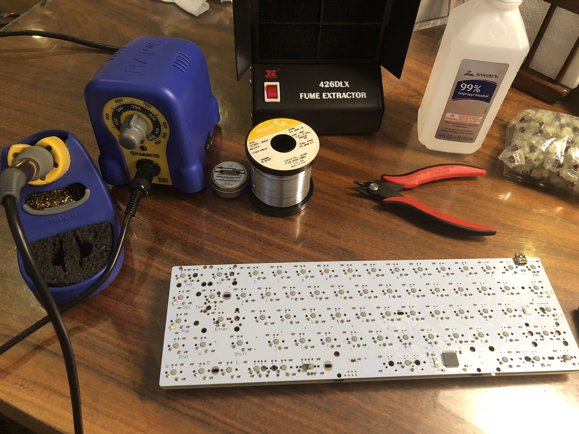
If you want, it’s not so hard to hand-wire a set of keys into the rows and columns of a keyboard, adding diodes for anti-ghosting. But it’s a lot easier to buy a PCB, which comes with the wires, the traces, the diodes, and a microcontroller (like an Arduino) already programmed to read the key matrix. We used the PCB for the Tada 68, which uses the QMK keyboard controller firmware.
We’d love to have fired up KiCad to design our own PCB, but we have our regular work too!
The plate
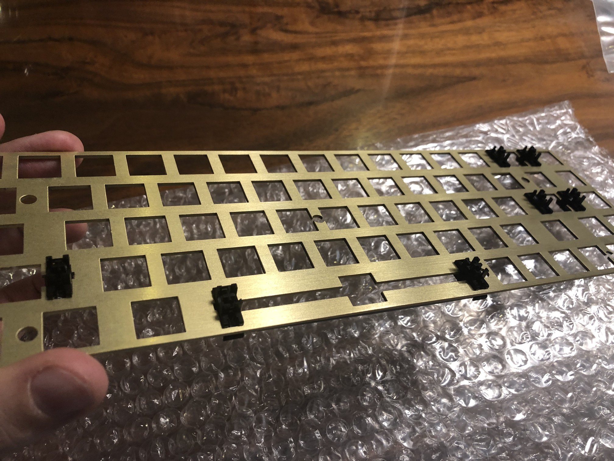
The plate was the first piece to be designed, since the case must be built around it. It’s simple: just a 1.5mm-thick sheet of brass with square holes in it, where you snap in your Cherry switches, and smaller round holes, for stabilizers. While the plate itself stabilizes the keyboard as a whole and gives it a nice heft, the “stabilizers” ensure that longer keys, like the space bar, have a consistent feel. (If you hit the left side of the key, you don’t want to feel like you’re pressing down on a see-saw.)
To build the plate, all we had to do was produce a CAD file and send it to Laser Boost, in Spain, who did the actual cutting.
Connecting the key switches to the plate was a matter of snapping them in, and then through-hole soldering each switch to the corresponding pad on underside of the PCB.
By far the bulk of the work went into designing and building the case.
The case
You can find plenty of pre-built cases for so-called compact “60%”-layout keyboards, but these layouts are missing arrow keys. For our purposes, that was a bridge too far; we prefer the rarer 68-key layout. But this put us into classic maker territory – with no way to buy an existing wooden case that matched our specifications, we had to build our own.
We based our design on this nice wooden keyboard, and began by building a simple 3D model in Rhino, just to get the measurements and clearances of the three main parts settled up front.
For the wood, we used a single large piece of 8-quarter walnut from the Boards & Beams lumber yard in Fairfield, NJ. We ran it through a planer and table saw to cut it down to size.
In the original design, we had little throwaway “tabs” on either side of the keyboard, each with a hole in it that could be used to anchor the block of wood to the gantry on the cutting machine. That way, when we flipped the piece upside down, we could be sure that it would continue to be aligned perfectly – which was necessary to cut the two halves of the hole where the USB cable connects to the PCB. But this step was dropped in later designs, where that hole was cut simply by turning the block of wood on its side.
The CNC router we used was a Shopbot Desktop MAX. In essence, you mount your block of material underneath the CNC to a table. You attach some kind of tool to the head of the machine – in this case, we used 1/4” and 1/8” square end mills. Then the machine moves on tracks in the X, Y, and Z directions, applying pressure to your material, and cutting it according to the precise instructions you provide via your CAD program. (For the cuts, we exported our Rhino model into Fusion 360 for its excellent CAD capabilities.)
The cut instructions are known as a “tool path,” and the first paths we used involved simple facing and contouring operations, basically making the face of our wood uniform and smooth. These are calibration steps for the later cuts. Using tool no. 4, the CNC machine does this by making consistent passes over the whole block.
The tool path for the “adaptive clearing path” cut, in which we actually carved out a space for PCB, plate, and mounting holes, was selected not just to cut the precise shape we wanted, but to minimize the amount of wear and tear on the tool itself, and to avoid throwing off unnecessary chips of material. You can see it here:
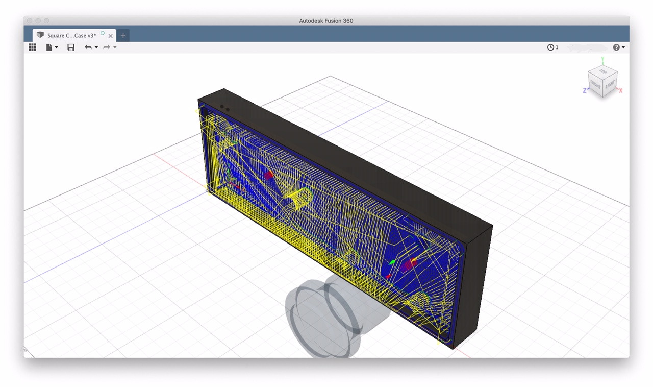
And here, you can see an simulation of what the actual cut looks like:
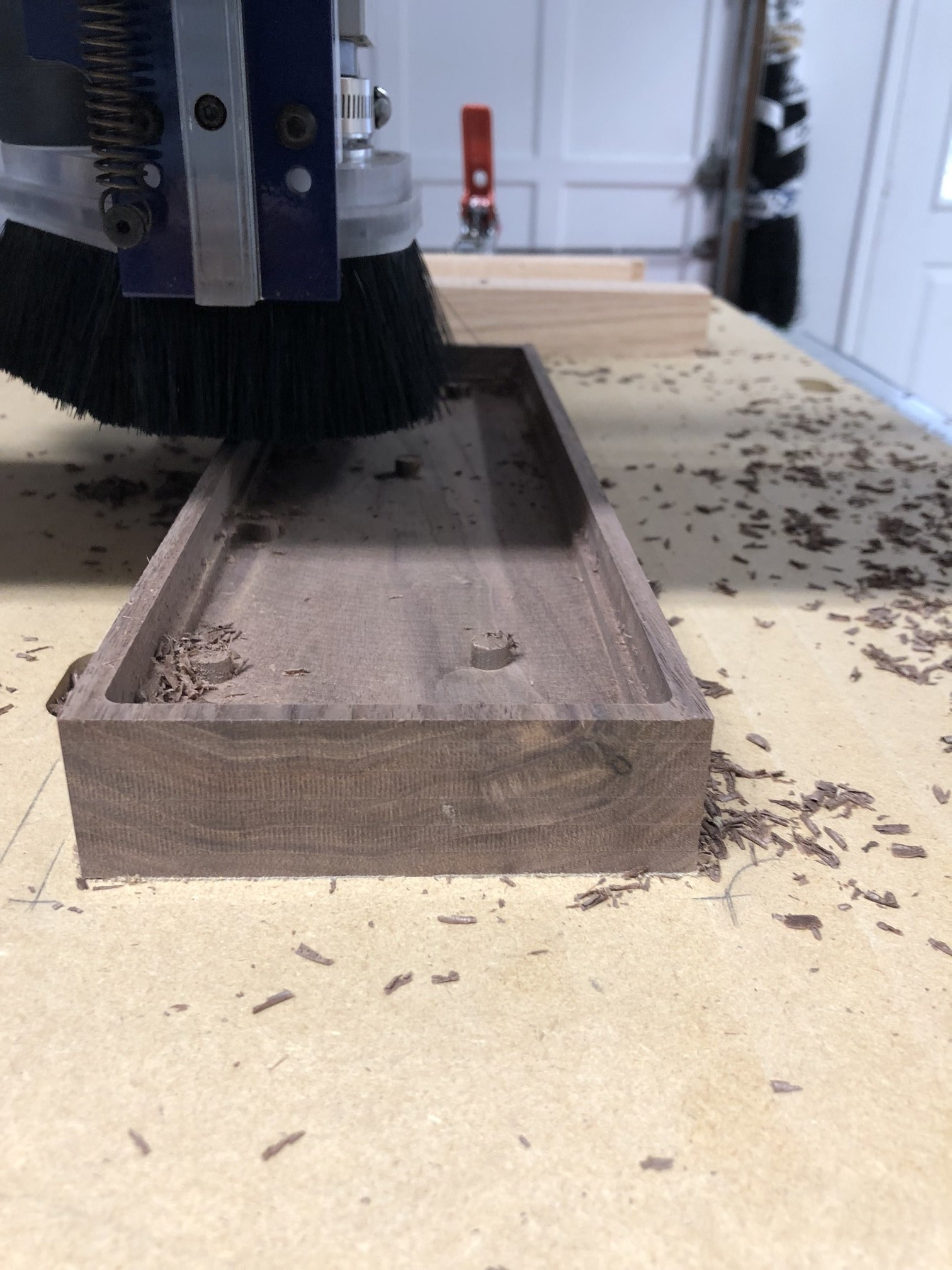
After this cut, there were still little bits of material left over where the quarter-inch tool was too large to go, especially around the small mounting holes. We cleaned these up with a second round of clearing using a smaller 1/8th-inch tool, and then oriented the wood on its side to carve out the port for the USB cable.
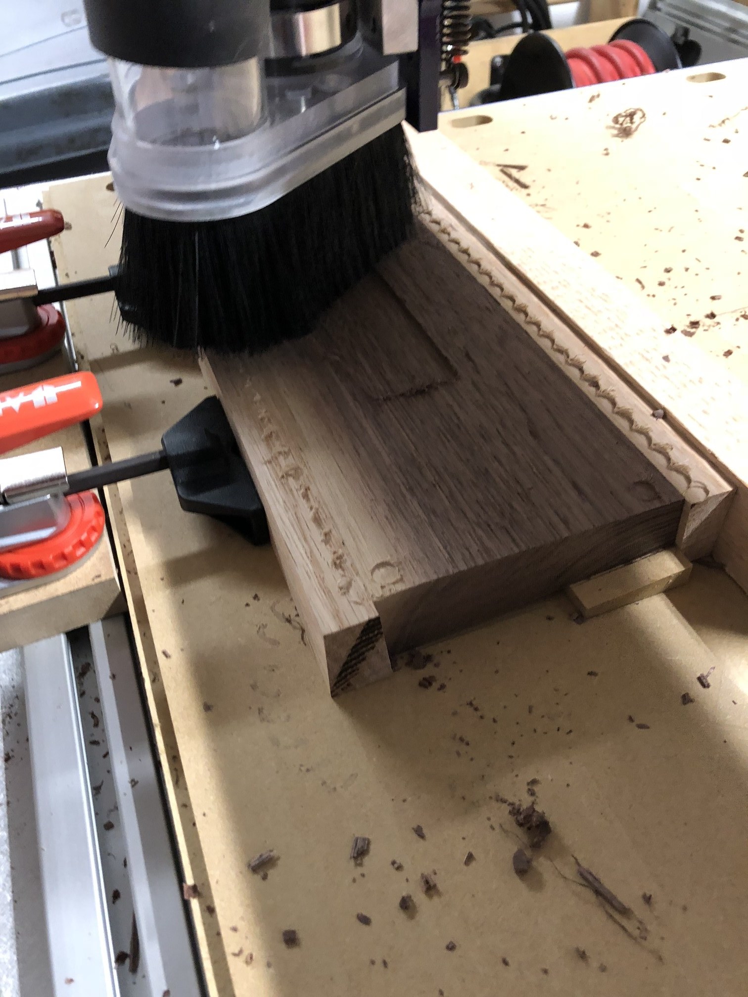
Finally, to give the keyboard a slight lean (for optimal wrist position) we flipped the case upside down, and did another facing operation, this time orienting the case with an angle in our gantry. Making multiple passes with a ball end tool, stepping down the angle, we were able to engineer a seamlessly smooth cut, and a 5-degree grade:
(We’re all still learning CNC, but found Michal Zalewski’s Guerilla Guide to CNC to be excellent!)
Assembly
Part of what gives the keyboards their solid feel is that there are hardly any parts to assemble. After placing the PCB/plate piece into the case, we mounted everything into place using Yardley threaded inserts, which are pressed into the holes we’d cut earlier. These have machine threads on the inside, which we used to screw the PCB to the case.
The decorative plate
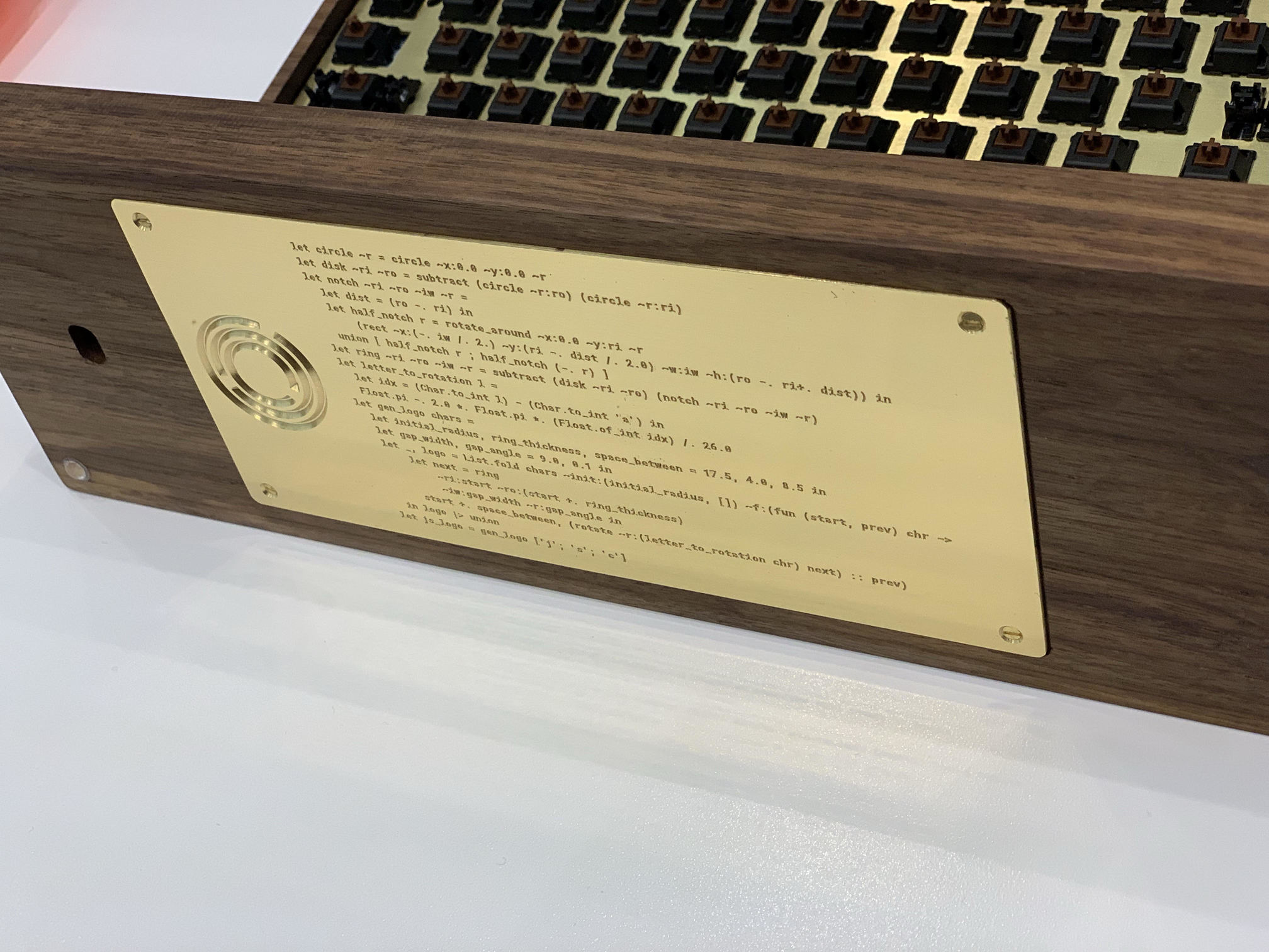
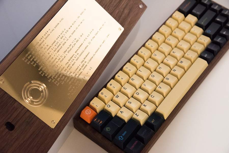
A Jane Street project wouldn’t be complete without a little OCaml. As a finishing touch, we designed a small decorative plate, also in brass, with the Jane Street logo. The twist is that the logo itself was defined programmatically via an OCaml DSL that sits on top of Signed Distance Functions.
Signed distance functions represent shapes as functions from a coordinate to the distance to that shape’s edge (positive if outside of the shape, negative if inside, 0.0 if exactly on the edge).
type shape = x:float -> y:float -> float
let circle ~cx ~cy ~r ~x ~y =
  let dx, dy = cx -. x, cy -. y in
  (Float.sqrt (dx *. dx +. dy *. dy)) -. r
let union ~a ~b ~x ~y =
  Float.min (a ~x ~y) (b ~x ~y)
Sampling these functions inside of Marching Squares gives us the poly-lines that we can give to CAD/CAM software to process the tool path for carving the logo into brass.
The code that sits beside it:
let circle ~r = circle ~x:0.0 ~y:0.0 ~r

let disk ~ri ~ro = subtract (circle ~r:ro) (circle ~r:ri)

let notch ~ri ~ro ~iw ~r =
  let dist = (ro -. ri) in
  let half_notch r = rotate_around ~x:0.0 ~y:ri ~r
      (rect ~x:(-. iw /. 2.) ~y:(ri -. dist /. 2.0) ~w:iw ~h:(ro -. ri+. dist)) in
  union [ half_notch r ; half_notch (-. r) ]

let ring ~ri ~ro ~iw ~r = subtract (disk ~ri ~ro) (notch ~ri ~ro ~iw ~r)

let letter_to_rotation l =
  let idx = (Char.to_int l) - (Char.to_int 'a') in
  Float.pi -. 2.0 *. Float.pi *. (Float.of_int idx) /. 26.0

let gen_logo chars =
  let initial_radius, ring_thickness, space_between = 17.5, 4.0, 8.5 in
  let gap_width, gap_angle = 9.0, 0.1 in
  let _, logo = List.fold chars ~init:(initial_radius, []) ~f:(fun (start, prev) chr ->
      let next = ring
          ~ri:start ~ro:(start +. ring_thickness)
          ~iw:gap_width ~r:gap_angle in
      start +. space_between, (rotate ~r:(letter_to_rotation chr) next) :: prev)
  in logo |> union

let js_logo = gen_logo ['j'; 's'; 'c']
We hope the hackathon contestants enjoy their prizes – we certainly had fun making them!